Frequently Asked Questions
Products
What is a velocity vibration transducer?
A velocity vibration transducer is an industrial sensor that measures the rate of structural movement during vibration, typically quantified in millimetres per second (mm/s) or inches per second (ips). They are widely used to monitor mid-frequency forces on rotating equipment like pumps, motors, fans, and turbines. Because velocity directly correlates to fatigue and mechanical stress, these transducers are the industry standard for identifying common balancing, misalignment, and structural looseness faults.
What is a seismic transducer?
A seismic transducer is a vibration sensor mounted directly onto an external machine casing or structural bearing housing to measure its absolute movement relative to earth. Utilizing an internal inertial mass, seismic transducers capture low-to-medium frequency vibrations without needing a static reference point. This makes them ideal for tracking structural defects, casing resonances, and mechanical imbalances on heavy, solid-bearing industrial machinery.
What is an accelerometer?
An accelerometer is a transducer that measures the rate of change of velocity (acceleration) of a vibrating structure, typically expressed in \(g\) or \(m/s^2\). Because acceleration emphasizes high-frequency energy, these sensors are vital for detecting early-stage rolling element bearing faults, gear mesh defects, and high-speed rotor anomalies. They allow reliability engineers to trend micro-shocks long before physical damage causes a catastrophic failure.
What are piezoelectric accelerometers?
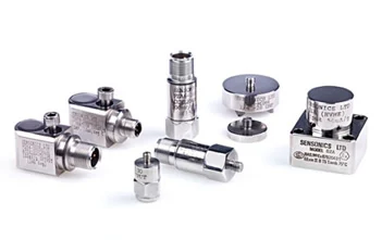
Piezoelectric accelerometers are solid-state sensors that use specialized crystal elements (such as quartz or engineered ceramics) to convert mechanical vibration into electrical signals. When subjected to vibrational stress, the crystal generates an electrical charge proportional to the acceleration force. These sensors are highly favoured in heavy industry because they feature no moving parts, offer an exceptionally wide frequency response, and deliver rugged, long-term reliability in harsh environments.
What is a proximity probe?
A proximity probe (also known as an eddy current probe) is a non-contact displacement sensor that measures the relative dynamic and static movement of a rotating shaft within its fluid-film bearings. Operating on electromagnetic induction principles, it tracks the microscopic gap changes between the probe tip and the target shaft. This makes proximity probes mandatory under API 670 for monitoring shaft vibration, axial thrust position, and oil-film stability in critical turbomachinery.
What is an LVDT sensor?
An LVDT (Linear Variable Differential Transformer) is a highly accurate, frictionless electromechanical transducer used to measure linear displacement and position. It converts the rectilinear motion of a magnetic core into a highly precise electrical signal. In power generation and industrial applications, LVDTs are primarily deployed to monitor steam turbine governor valve positions, hydraulic actuator strokes, and critical turbine casing thermal expansion.
What is a capacitive air gap sensor?
A capacitive air gap sensor is a specialized non-contact measurement device used to monitor the exact dynamic distance between the rotor poles and the stator core in large hydro-generators and electric motors. By measuring changes in electrical capacitance as the rotor spins, the system detects structural distortion, frame out-of-roundness, and magnetic imbalances. Continuous air gap monitoring prevents catastrophic rotor-to-stator contact and optimizes generator efficiency.
Turbine Monitoring & Protection
What is a Turbine Supervisory Instrumentation (TSI) system?
A Turbine Supervisory Instrumentation (TSI) system is a dedicated, high-integrity monitoring network that continuously tracks the mechanical health and thermal behaviour of critical steam and gas turbomachinery. It aggregates real-time data from an array of specialized sensors to evaluate shaft vibration, rotor position, rotational speed, differential expansion, and eccentricity. Operating as a critical line of defence, a TSI system ensures that massive power generation and industrial turbines operate safely within tight mechanical tolerances.
Why is a Turbine Supervisory Instrumentation (TSI) system important?
A TSI system is essential because it prevents catastrophic structural failures, protects multi-million pound assets, and minimizes unplanned outages. Turbomachinery undergoes extreme thermal and mechanical stress during start-up, run-up, and changing load conditions. By providing real-time data on rotor-to-stator alignments and thermal expansion, the TSI system allows operators to detect micro-faults early, optimize maintenance windows, and maximize turbine availability.
What critical parameters does a TSI system monitor?
A comprehensive TSI system monitors an array of complex mechanical variables, including:
- Shaft Radial Vibration: Detects dynamic imbalances, shaft bow, fluid-film bearing instability, and oil whirl.
- Axial Thrust Position: Measures micro-movements of the rotor shaft relative to the thrust bearing to prevent internal collisions.
- Differential Expansion: Evaluates the relative thermal growth difference between the fast-heating rotor and the heavy casing.
- Rotor Eccentricity: Tracks the physical shaft bow or warp, which is critical during low-speed barring (turning gear) operations.
- Casing Expansion: Monitors the absolute thermal movement of the outer turbine housing relative to the foundation.
- Rotational Speed & Overspeed Protection: Measures RPM to ensure the turbine never exceeds its safe structural design limits.
- Bearing & Metal Temperature: Monitors bearing metal and other critical temperatures to detect overheating and abnormal operating conditions.
- Valve Position: Tracks the position of steam or governor valves using devices such as LVDTs to ensure accurate turbine control and operation.
- Dynamic Pressure: Measures pressure fluctuations within the steam or gas path to identify process instability and abnormal operating conditions.
Can a TSI system interface with a plant Distributed Control System (DCS)?
Yes, modern TSI systems are designed to seamlessly integrate with plant Distributed Control Systems (DCS), Programmable Logic Controllers (PLCs), and broader asset management software. This connectivity is typically achieved through high-speed digital fieldbus protocols (such as Modbus TCP/IP, Profibus, or OPC UA) alongside standard analogue outputs such as buffered 4–20 mA current loops and 0–10 Vdc voltage outputs. This ensures safety-critical trip signals remain autonomous while giving control room operators full visibility of trend data.
What is an overspeed protection system?
An overspeed protection system is a safety-critical loop that monitors a turbine's rotational speed and automatically executes an emergency shutdown if safe RPM thresholds are breached. Utilizing high-speed proximity sensors or magnetic pickups paired with multi-channel voting logic (such as 2-out-of-3), it commands rapid-response trip valves to cut fuel or steam supply in milliseconds. This system prevents catastrophic centrifugal destruction of the turbine blades and rotor.
Seismic monitoring, recording, and protection
What is a seismic monitoring system?
A seismic monitoring system is an integrated network of specialist, high-integrity instruments designed to detect, measure, and log ground-borne vibrations. The system captures real-time dynamic data caused by earthquakes or man-made events like blasting or mining. A typical Sensonics system combines high-sensitivity triaxial sensors with multi-channel recording units to provide automated event capture, time-history data, FFT analysis, and spectral response analysis.
How do seismic switches work?
Seismic switches (such as the Sensonics SA-3) are triaxial vibration-detection devices mounted rigidly to a building's structure. They continually monitor the ground acceleration across three perpendicular axes (X, Y, and Z). When the vibration amplitude on any axis exceeds a pre-set structural safety threshold, the switch instantly actuates its internal, high-integrity alarm relays. To prevent false alarms, these switches can be configured into a 2-out-of-3 (2oo3) voting logic loop. This ensures automated safety reactions trigger only when multiple sensors confirm the event.
What is the purpose of a seismic protection system?
The primary purpose of a seismic protection system is to automatically minimize risks to people, plant assets, and the local environment during a heavy seismic event. Rather than just recording the earthquake, a protection system directly acts as an automated safety layer. It instantly activates structural alarms and triggers fail-safe, emergency shutdown procedures for hazardous processes before catastrophic structural failure can occur.
Why is seismic monitoring important for critical infrastructure?
Critical infrastructure—including nuclear power plants, oil and gas facilities, power generation plants, dams, mining operations and chemical facilities—is highly vulnerable to severe environmental forces. Seismic monitoring provides the precise data required for both immediate post-event risk assessment and long-term regulatory compliance. It allows operators to evaluate structural fatigue, verify structural integrity, and make informed, data-driven decisions on whether an industrial asset is safe to continue operating after a shake.
What is the difference between seismic monitoring and seismic protection?
- Seismic Monitoring is a diagnostic, data-gathering process. It focuses on measuring, recording, and analysing wave frequencies, peak accelerations, and structural responses for post-event evaluation and structural health history.
- Seismic Protection is an active, safety-critical control process. It uses safety switches and voting relay circuits to execute immediate physical actions, like shutting down a pipeline, isolating hazardous gasses, or tripping a reactor the moment a seismic threshold is breached.
What sensors are used in seismic monitoring systems?
Sensonics utilizes high-integrity piezoelectric accelerometers (such as the SP4/SP5 seismic sensors) for strong-motion seismic protection. Piezoelectric sensors are highly preferred for industrial safety because they have no moving internal parts, resulting in superior long-term reliability and aging characteristics. Additionally, these sensors feature a unique, built-in mechanical self-test function. This allows operators to remotely inject a physical excitation to check the health and accuracy of the sensor element without taking the safety system offline.
Can seismic monitoring systems be integrated with a DCS or SCADA system?
Yes. While seismic protection loops must operate as an independent, hardwired fail-safe system to meet strict safety regulations, the monitoring data seamlessly integrates into plant-wide control architectures. Sensonics systems can provide robust current loop outputs (4-20mA) for each axis to trace real-time seismic waveforms, alongside dedicated digital relays for fault and event indications. This allows the primary Distributed Control System (DCS) or SCADA platform to log trends, trigger control room alarms, and display system health status centrally.
Can I use this module with existing HubSpot themes?
Yes, this module integrates smoothly with any HubSpot theme, complementing your design and functionality needs.
Condition Monitoring
What is industrial condition monitoring?
Industrial condition monitoring is the process of assessing the health and performance of machinery using one or more diagnostic technologies to identify developing faults before they result in failure. Rather than relying solely on scheduled maintenance, it enables maintenance decisions to be based on the actual condition of equipment.
Condition monitoring encompasses a range of techniques, including vibration monitoring, temperature measurement, oil and lubricant analysis, ultrasound, infrared thermography, motor current and electrical signature analysis, and other diagnostic methods. Depending on the application, these technologies may be used individually or in combination to provide a comprehensive picture of machine health.
Vibration monitoring is one of the most widely used condition monitoring techniques for rotating machinery, providing early warning of faults such as imbalance, misalignment, bearing damage, gear wear, looseness and resonance. By analysing trends and deviations from normal operating conditions, engineers can plan maintenance proactively, reduce unplanned downtime and extend equipment life.

What are the best condition monitoring methods for rotating machinery?
The most effective machinery condition monitoring techniques include:
- Vibration Analysis: The primary method for identifying balancing issues, bearing damage, gear wear, and shaft misalignments.
- Shaft Displacement Tracking: Uses non-contact probes to monitor dynamic oil-film stability and rotor clearances.
- Thermal Monitoring: Tracks bearing temperatures and winding insulation degradation via RTDs or infrared thermography.
- Oil Condition & Debris Analysis: Evaluates lubricant degradation, moisture ingress, and microscopic wear particles in gearboxes.
- Acoustic Emission Testing: Captures high-frequency stress waves to detect micro-cracking and early-stage structural faults.
What is Condition-Based Maintenance (CBM)?
Condition-Based Maintenance (CBM) is an asset management strategy where maintenance actions are triggered only when real-time sensor data indicates equipment performance is degrading or nearing failure. Instead of performing costly service routines on arbitrary calendar dates, CBM relies on live diagnostics to ensure components are only repaired or replaced when necessary, optimizing maintenance budgets and asset lifespans.
How does predictive maintenance differ from preventive maintenance?
Preventive maintenance operates on fixed, time-based intervals or run-hours (e.g., changing a bearing every 12 months), regardless of the component's actual health. In contrast, predictive maintenance utilizes continuous condition monitoring data, advanced diagnostics, and statistical modeling to accurately forecast when a machine will fail. This allows maintenance teams to schedule interventions precisely before failure occurs, minimizing downtime and eliminating unnecessary work.
Wind Turbine Monitoring
Why is condition monitoring important for wind turbines?
Condition monitoring is critical for wind turbines because their isolated locations—especially offshore—make physical inspections and unscheduled maintenance incredibly expensive. Turbine drivetrains are exposed to erratic, high-stress aerodynamic loads that accelerate wear on gearboxes, main bearings, and generators. Early detection of these faults via remote sensors allows operators to avoid catastrophic failures, organize parts in advance, and coordinate heavy-lift crane vessels during lower-wind seasons.
What specific sensors are used on wind turbines?
Modern wind turbines rely on an array of specialized monitoring sensors, including:
- Low-Frequency Accelerometers: Mounted on the main bearing, nacelle, and tower structure to monitor structural vibration, aerodynamic loading, and low-frequency mechanical faults.
- High-Frequency Accelerometers: Mounted on gearbox stages and generator bearings to detect gear pitting, bearing wear, and other high-frequency defects.Inductive Wear Debris Sensors: Integrated into the main gearbox oil loop to count ferrous and non-ferrous metal particles.
- Oil Quality & Dielectric Sensors: Continuous monitoring tools that track lubrication breakdown, viscosity shifts, and moisture ingress.
- Fiber Optic Strain Gauges: Embedded along the rotor blades to measure structural twisting, aerodynamic loading, and ice accumulation.
Can vibration monitoring detect wind turbine gearbox faults?
Yes, vibration monitoring is the industry's most reliable method for detecting wind turbine gearbox faults. Because wind turbine gearboxes utilize complex planetary and high-speed gear stages, they generate distinct, high-frequency signatures. Advanced vibration analysis—utilizing techniques like enveloping and demodulation—can isolate micro-shocks from broken gear teeth, bearing spalling, and shaft misalignment months before the gearbox sustains terminal damage.
How can Artificial Intelligence (AI) improve wind turbine monitoring?
Artificial Intelligence (AI) and machine learning models enhance wind turbine monitoring by automating the analysis of massive, multi-variable SCADA and vibration data streams. AI algorithms can identify subtle, multi-variable anomalies—such as a minor temperature rise paired with a specific high-frequency vibration shift—that human analysts might miss. This enables automated fault pattern recognition, reduces false alarms, and optimizes fleet-wide maintenance schedules based on predictive remaining useful life (RUL) modelling.
Technical & Compliance
Why is sensor calibration important?
Sensor calibration ensures data integrity and prevents costly false alarms. Over time, internal piezoelectric crystals and micro-electronics naturally drift. Regular calibration maintains precise sensitivity and phase tracking across the entire frequency range.
How often should vibration sensors be calibrated?
Calibration intervals depend on the application, criticality and site maintenance strategy. Many industrial installations adopt intervals of between one and three years, although safety-critical applications may require more frequent verification in accordance with site procedures and regulatory requirements.
What is API 670?
API 670 is the globally recognized standard published by the American Petroleum Institute that defines the minimum requirements for a Machinery Protection System (MPS). It dictates how critical rotating machinery—such as turbines, compressors, and pumps—must be monitored for vibration, temperature, and overspeed.
Are Sensonics systems API 670 compliant?
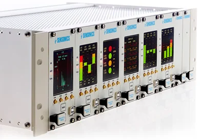
Yes. Sensonics design philosophy for machinery protection systems aligns strictly with the API 670 standard (Machinery Protection Systems). While API 670 acts primarily as an American purchasing specification, Sensonics structures its machinery protection racks—such as the Sentry G3 system—to fully satisfy these strict hardware, configuration, and reliability guidelines.
What is IEC 61508?
IEC 61508 is the foundational international standard governing the functional safety of electrical, electronic, and programmable electronic safety-related systems (E/E/PE). It provides a rigorous framework for assessing, designing, and operating safety systems to reduce risk to an acceptable level.
What is a SIL-rated monitoring system?
A SIL-rated monitoring system is a protection system that has been independently certified to meet a specific Safety Integrity Level (SIL) as defined by IEC 61508. SIL levels scale from SIL 1 (lowest risk reduction) to SIL 4 (highest risk reduction), indicating the system's target safety performance.
Orders & Support
How do I request a quotation?
Contact sales@sensonics.co.uk with details of your machinery, operating conditions and monitoring requirements.
What information should I provide for an enquiry?
To help us recommend the most suitable solution, provide:
- Machine type
- Application details
- Existing sensor arrangements
- Required measurements
- Drawings or technical documentation where available
Can Sensonics provide custom solutions?
Yes. Sensonics offers complete turnkey projects and bespoke designs tailored to your specific engineering requirements.
Do you offer calibration services?
Yes. Sensonics offers comprehensive support and traceable calibration services for all vibration monitoring and protection equipment.
Do you provide international support?
Yes. Sensonics supports customers worldwide through its network of offices, partners and distributors.
Our services
YOU MIGHT ALSO BE INTERESTED IN...
Turbine Supervisory Instrumentation
Industrial Sensors
Speed Monitoring Solutions